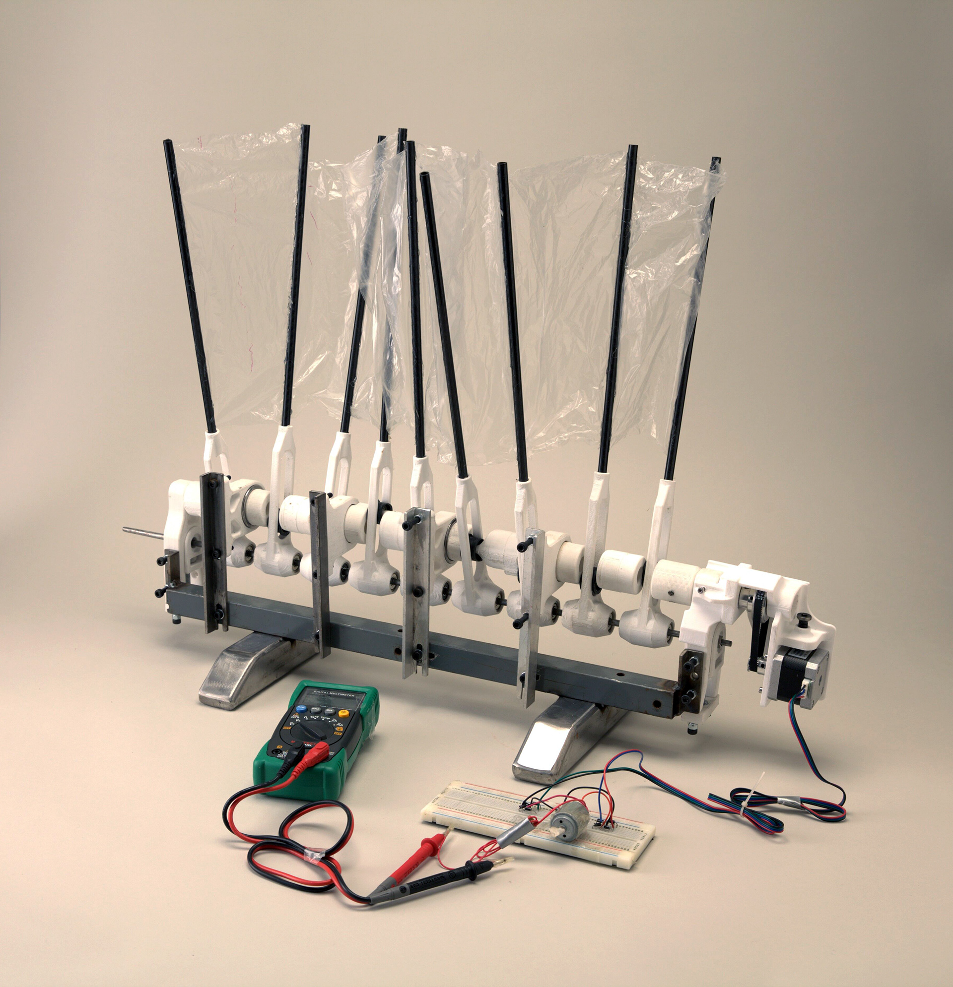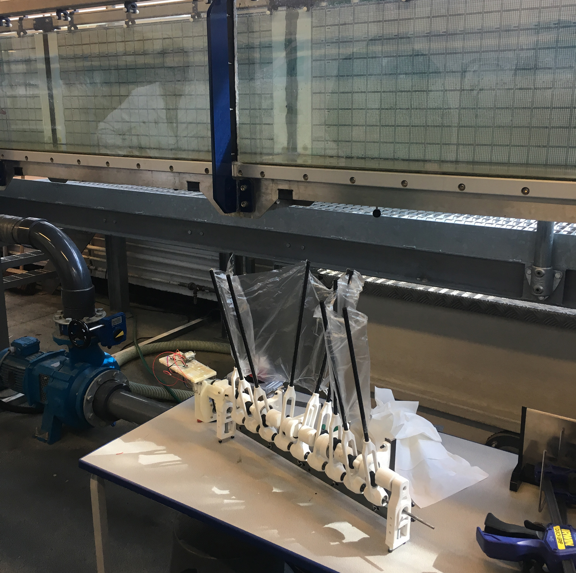
Above and below: Testing of the first functional, small scale prototype

Below: Test footage of the small scale prototype in both the Brunel University flow tank and the river avon. The flow tank tests were run from stationary to 0.8m/s flow speed, and the tests in the actual river flow were the same (error on account of rough measurement techniques). 1.97Kw was recorded at a flow rate of 0.8m/s, after which the generator system stalled. Potentially more would be feasable on this scale.
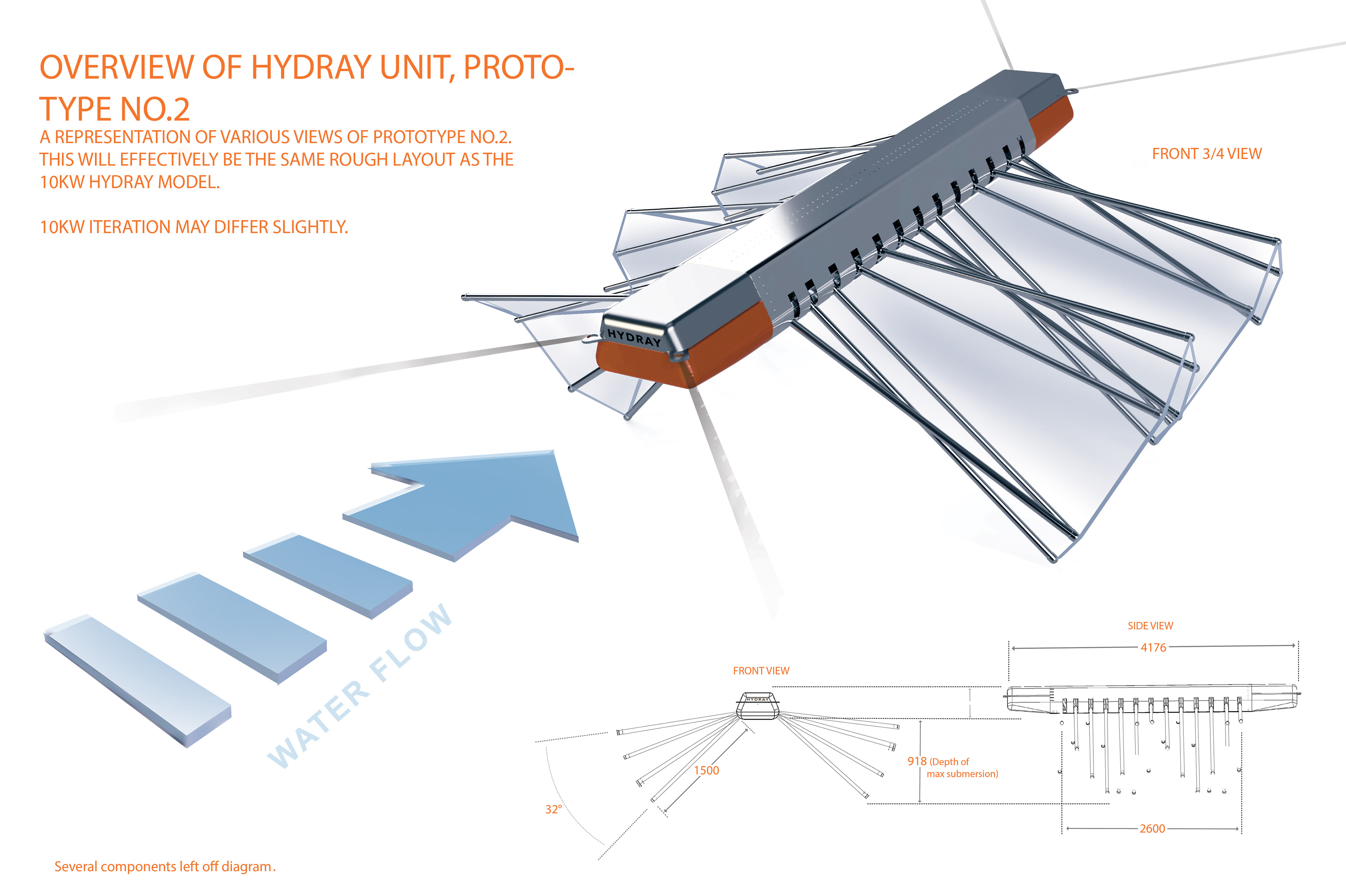
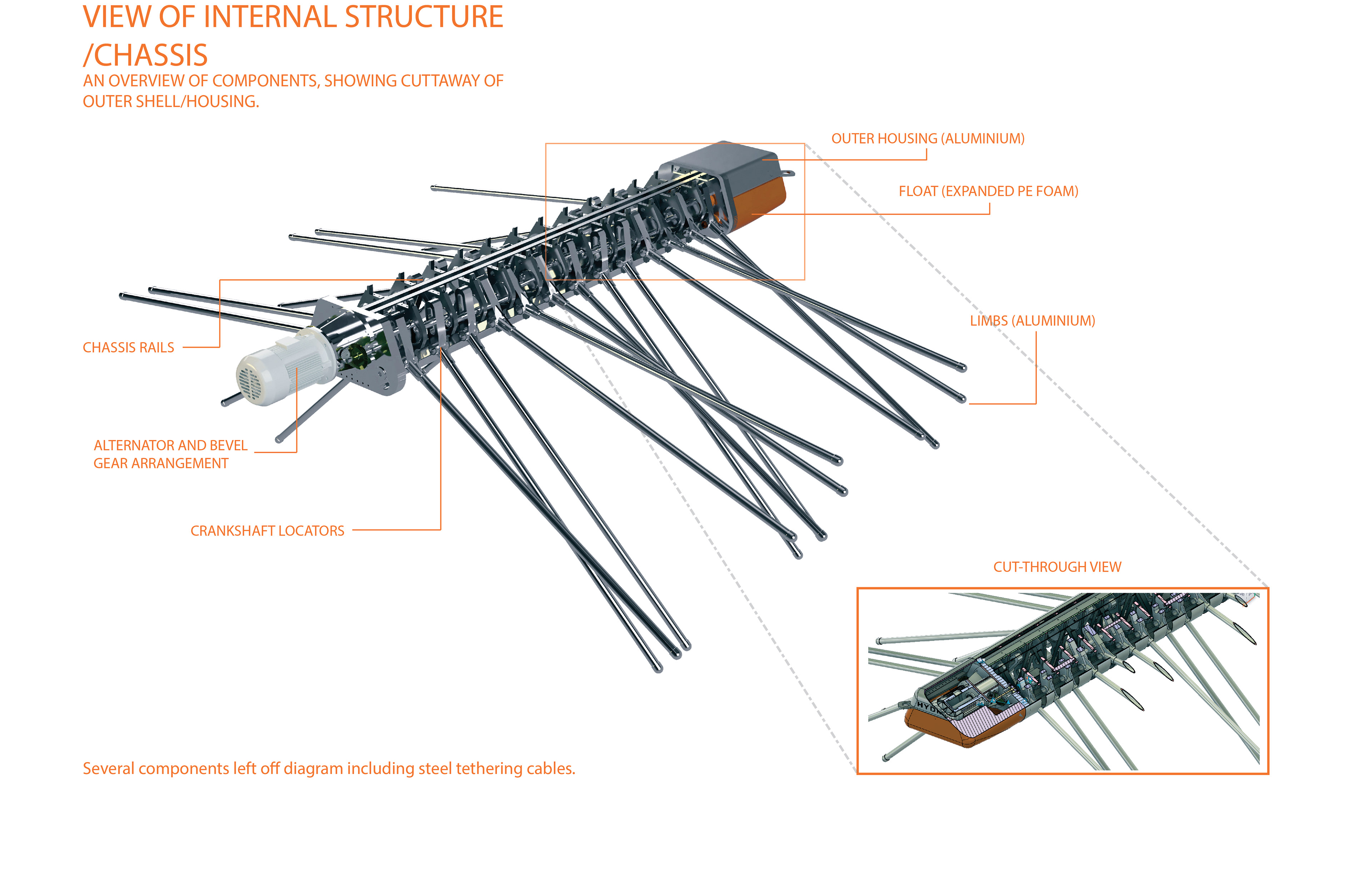
After various scale-up calculations and in-depth costing analysis, I have designed a 10kW Hydray device, posing as potentially one of the most competitively priced renewable energy solutions on offer at £0.0178/Kwh, along with one of the lowest Co2 footprints per Kw at 0.016kg/kw. I therefor plan to pursue the concepts development with building and testing of this Large scale prototype, in order to optimise the concepts systems and further gauge how effective the Hydray could be on a large, industrial-scale with an economically viable and environmentally attractive energy output.
Below: Distribution and Application Overview Map - This map is a representation of how the Hydray devices would be used in conjunction with other Hydray devices in series, effectively all working individually to provide a combined net energy output. This spreads out the individual environmental detriment of a single large hydro electric system (a large turbine derived system/hydroelectric dam for example), allowing less disruption in any one location and less overall flow loss.

The Hydray poses as a low-obtrusive hydroelectric energy transfer device, with its operation requiring only natural, uni-directional flowing water (rivers and estuaries being prime examples), and therefor there is no need to alter the related body of water in any way. Its slow oscillating membraned surface is the only external environmental-interface, with no immediate impact to flora and fauna. It is also non-perminant and flexible in its orientation and characteristics dependant on the specifics of its implementation.
Below: Prototype no.1.3 with simple alternator set up, also showing clear view of offset crankshaft.